Structure gauge

| Part of a series on |
| Rail transport |
|---|
 |
| |
| Infrastructure |
| |
| Service and rolling stock |
|
| Special systems |
| |
| Miscellanea |
| |


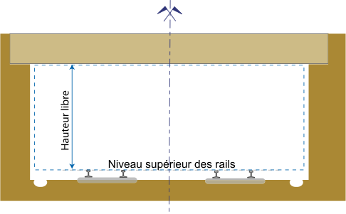
A structure gauge, also called the minimum structure outline, is a diagram or physical structure that sets limits to the extent that bridges, tunnels and other infrastructure can encroach on rail vehicles. It specifies the height and width of station platforms, tunnels and bridges, and the width of the doors that allow access to a warehouse from a rail siding. Specifications may include the minimum distance from rail vehicles to railway platforms, buildings, lineside electrical equipment cabinets, signalling equipment, third rails or supports for overhead lines.[1]
A related but separate gauge is the loading gauge: a diagram or physical structure that defines the maximum height and width dimensions in railway vehicles and their loads. The difference between these two gauges is called the clearance. The specified amount of clearance makes allowance for wobbling of rail vehicles at speed or the shifting of vehicles on curves; consequently, in some circumstances a train may be permitted to go past a restricted clearance at very slow speed.
Road traffic application
[edit]The term can also be applied to the minimum size of road tunnels, the space beneath overpasses and the space within the superstructure of bridges, as well as doors into automobile repair shops, bus garages, filling stations, residential garages, multi-storey car parks, overhangs at drive-throughs and warehouses.[citation needed]
Eurocode 1: Actions on structures has a definition of "physical clearance" between roadway surface and the underside of bridge element. The code also defines the clearance that is shorter than the physical clearance to account for sag curves, bridge deflection and expected settlements with a recommendation of minimum clearance of 5 metres (16 ft 5 in).[2] In UK, the "standard minimum clearance" for structures over public highways is 16 feet 6 inches (5.03 m).[3] In United States, the "minimum vertical clearance" of overpasses on Interstate Highway System is 16 feet (4.9 m).[4]
Gallery
[edit]- Structure gauges
- Structure gauge for a bridge or other wayside objects
hauteur libre = clear height
Niveau superieur des rails = Top of rails - German structure gauge showing (left side) limits to encroachment of the rail vehicle envelope on mainlines and (right side) secondary tracks
See also
[edit]- Air draft, applies to bridges across navigable waterways
- Berne gauge
- Bridge
- Clearance car
- Cut
- Disadvantages of third rail (additional infrastructure restrictions)
- Engineering tolerance
- List of bridges known for strikes
- Loading gauge
- Railway platform
- Railway platform height
- Tunnel
- Wayobjects
References
[edit]- ^ "Structure Gauge and Kinematic Envelope".
- ^ Eurocode 1 - Actions on structures - Part 1-7: General actions - Accidental actions (PDF). The European Union. July 2006. Retrieved 31 August 2023.
- ^ Preventing of Strikes on Bridge Over Highways - A Protocol for Highway Managers & Bridge Owners (PDF) (2 ed.). Network Rail on behalf of Bridge Strike Prevention Group. p. 6. Retrieved 29 August 2023.
- ^ "Right of Passage: The Controversy Over Vertical Clearance on the Interstate System". U.S. Department of Transportation Federal Highway Administration. Retrieved 27 August 2023.
External links
[edit]- Transport Canada, Standard Respecting Railway Clearance
- GLOSSARY OF TERMS USED IN RAILROAD HIGH AND WIDE CLEARANCES
- Railway line clearances and car dimensions including weight ..., Volumes 87-90
- www.ipm.fraunhofer.de/railway

