Hot air engine
 From Wikipedia the free encyclopedia
| Thermodynamics |
|---|
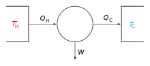 |


A hot air engine[1] (historically called an air engine or caloric engine[2]) is any heat engine that uses the expansion and contraction of air under the influence of a temperature change to convert thermal energy into mechanical work. These engines may be based on a number of thermodynamic cycles encompassing both open cycle devices such as those of Sir George Cayley[3] and John Ericsson[4] and the closed cycle engine of Robert Stirling.[5] Hot air engines are distinct from the better known internal combustion based engine and steam engine.
In a typical implementation, air is repeatedly heated and cooled in a cylinder and the resulting expansion and contraction are used to move a piston and produce useful mechanical work.
Definition[edit]
.jpg)
The term "hot air engine" specifically excludes any engine performing a thermodynamic cycle in which the working fluid undergoes a phase transition, such as the Rankine cycle. Also excluded are conventional internal combustion engines, in which heat is added to the working fluid by combustion of fuel within the working cylinder. Continuous combustion types, such as George Brayton's Ready Motor and the related gas turbine, could be seen as borderline cases.
History[edit]
The expansive property of heated air was known to the ancients. Hero of Alexandria's Pneumatica describes devices that might be used to automatically open temple doors when a fire was lit on a sacrificial altar. Devices called hot air engines, or simply air engines, have been recorded from as early as 1699. In 1699, Guillaume Amontons (1663–1705) presented, to the Royal Academy of Sciences in Paris, a report on his invention: a wheel that was made to turn by heat.[6] The wheel was mounted vertically. Around the wheel's hub were water-filled chambers. Air-filled chambers on the wheel's rim were heated by a fire under one side of the wheel. The heated air expanded and, via tubes, forced water from one chamber to another, unbalancing the wheel and causing it to turn.
See:
- Amontons (20 June 1699) "Moyen de substituer commodement l'action du feu, à la force des hommes et des chevaux pour mouvoir les machines" (Means of conveniently substituting the action of fire for the force of men and horses in order to move [i.e., power] machines), Mémoires de l'Académie Royale des Sciences, pages 112-126. The Mémoires appear in the Histoire de l'Académie Royale des Sciences, année 1699, which was published in 1732. The operation of Amontons' moulin à feu (fire mill) is explained on pages 123-126; his machine is illustrated on the plate following page 126.
- For an account of Amontons' fire-powered wheel in English, see: Robert Stuart, Historical and Descriptive Anecdotes of Steam-engines and of Their Inventors and Improvers (London, England: Wightman and Cramp, 1829), vol. 1, pages 130-132; an illustration of the machine appears on [7] around the time when the laws of gasses were first set out, and early patents include those of Henry Wood, Vicar of High Ercall near Coalbrookdale Shropshire (English patent 739 of 1759) and Thomas Mead, an engineer from Sculcoats Yorkshire (English patent 979 of 1791),[8] the latter in particular containing the essential elements of a displacer type engine (Mead termed it the transferrer). It is unlikely that either of these patents resulted in an actual engine and the earliest workable example was probably the open cycle furnace gas engine of the English inventor Sir George Cayley c. 1807[9][10]
It is likely that Robert Stirling's air engine of 1818, which incorporated his innovative Economiser (patented in 1816) was the first air engine put to practical work.[11] The economiser, now known as the regenerator, stored heat from the hot portion of the engine as the air passed to the cold side, and released heat to the cooled air as it returned to the hot side. This innovation improved the efficiency of Stirling's engine and should be present in any air engine that is properly called a Stirling engine.
Stirling patented a second hot air engine, together with his brother James, in 1827. They inverted the design so that the hot ends of the displacers were underneath the machinery and they added a compressed air pump so the air within could be increased in pressure to around 20 atmospheres. It is stated by Chambers to have been unsuccessful, owing to mechanical defects and to “the unforeseen accumulation of heat, not fully extracted by the sieves or small passages in the cool part of the regenerator, of which the external surface was not sufficiently large to throw off the unrecovered heat when the engine was working with highly compressed air.”
Parkinson and Crossley, English patent, 1828 came up with their own hot air engine. In this engine the air-chamber is partly exposed, by submergence in cold water, to external cold, and its upper portion is heated by steam. An internal vessel moves up and down in this chamber, and in so doing displaces the air, alternately exposing it to the hot and cold influences of the cold water and the hot steam, changing its temperature and expansive condition. The fluctuations cause the reciprocation of a piston in a cylinder to whose ends the air-chamber is alternately connected.
In 1829 Arnott patented his air expansion machine where a fire is placed on a grate near the bottom of a close cylinder, and the cylinder is full of fresh air recently admitted. A loose piston is pulled upwards so that all the air in the cylinder above will be made to pass by a tube through the fire, and will receive an increased elasticity tending to the expansion or increase of volume, which the fire is capable of giving it.
He is followed the next year (1830) by Captain Ericsson who patented his second hot air engine. The specification describes it more particularly, as consisting of a “circular chamber, in which a cone is made to revolve on a shaft or axis by means of leaves or wings, alternately exposed to the pressure of steam; these wings or leaves being made to work through slits or openings of a circular plane, which revolves obliquely to, and is thereby kept in contact with the side of the cone.”
Ericsson built his third hot air engine (the caloric engine) in 1833 "which excited so much interest a few years ago in England; and which, if it should be brought into practical operation, will prove the most important mechanical invention ever conceived by the human mind, and one that will confer greater benefits on civilized life than any that has ever preceded it. For the object of it is the production of mechanical power by the agency of heat, at an expenditure of fuel so exceedingly small, that man will have an almost unlimited mechanical force at his command, in regions where fuel may now be said hardly to exist".
1838 sees the patent of Franchot hot air engine, certainly the hot air engine that was best following the Carnot requirements.
So far all these air engines have been unsuccessful, but the technology was maturing. In 1842, James Stirling, the brother of Robert, build the famous Dundee Stirling Engine. This one at least lasted 2–3 years but then was discontinued due to improper technical contrivances. Hot air engines is a story of trials and errors, and it took another 20 years before hot air engines could be used on an industrial scale. The first reliable hot air engines were built by Shaw, Roper, Ericsson. Several thousands of them were built.
Commercial Manufacturers[edit]
Hot engines found a market for pumping water (mainly to a household water tank) as the water inlet provided the cold required to maintain the temperature difference, though they did find other commercial uses.
- Hayward, Tyler & Co of London. Engines for pumping water and working Punkahs c1876-1883.[12]
- Hayward-Tyler & Co of London. Domestic water supply (Rider's patent) c1888-1901.[13]
- W.H. Bailey & Co, Salford. Engines for pumping domestic water and operating stable machinery c1885-1887[14]
- Adam Woodward & Sons, Ancoats, Manchester. Robinson's patent. c1887[15]
- Norris & Henty, London. Resellers of 'Robinson' type pumping engines. c1898-1901[16]
- C.H. Delamater & Co, Delamater Iron Works, New York. 'Rider' and 'Ericsson' type engine. 1870s-1898
- Rider Engine Company, Walden, New York. 1879-1898
- Rider-Ericsson Engine Company, Walden, New York. 1898-
Thermodynamic cycles[edit]
A hot air engine thermodynamic cycle can (ideally) be made out of 3 or more processes (typically 4). The processes can be any of these:
- isothermal process (at constant temperature, maintained with heat added or removed from a heat source or sink)
- isobaric process (at constant pressure)
- isometric / isochoric process (at constant volume)
- adiabatic process (no heat is added or removed from the working fluid)
- isentropic process, reversible adiabatic process (no heat is added or removed from the working fluid - and the entropy is constant)
- isenthalpic process (the enthalpy is constant)
Some examples (not all hot air cycles, as defined above) are as follows:
| Cycle | Compression, 1→2 | Heat addition, 2→3 | Expansion, 3→4 | Heat rejection, 4→1 | Notes |
|---|---|---|---|---|---|
| Power cycles normally with external combustion - or heat pump cycles: | |||||
| Bell Coleman | adiabatic | isobaric | adiabatic | isobaric | A reversed Brayton cycle |
| Carnot | isentropic | isothermal | isentropic | isothermal | Carnot heat engine |
| Ericsson | isothermal | isobaric | isothermal | isobaric | The second Ericsson cycle from 1853 |
| Rankine | adiabatic | isobaric | adiabatic | isobaric | Steam engines |
| Hygroscopic | adiabatic | isobaric | adiabatic | isobaric | |
| Scuderi | adiabatic | variable pressure and volume | adiabatic | isochoric | |
| Stirling | isothermal | isochoric | isothermal | isochoric | Stirling engines |
| Manson | isothermal | isochoric | isothermal | isochoric then adiabatic | Manson and Manson-Guise engines |
| Stoddard | adiabatic | isobaric | adiabatic | isobaric | |
| Power cycles normally with internal combustion: | |||||
| Atkinson | isentropic | isochoric | isentropic | isochoric | Differs from Otto cycle in that V1 < V4. |
| Brayton | adiabatic | isobaric | adiabatic | isobaric | Ramjets, turbojets, -props, and -shafts. Originally developed for use in reciprocating engines. The external combustion version of this cycle is known as the first Ericsson cycle from 1833. |
| Diesel | adiabatic | isobaric | adiabatic | isochoric | Diesel engine |
| Humphrey | isentropic | isochoric | isentropic | isobaric | Shcramjets, pulse- and continuous detonation engines |
| Lenoir | isochoric | adiabatic | isobaric | Pulse jets. 1→2 accomplishes both the heat rejection and the compression. Originally developed for use in reciprocating engines. | |
| Otto | isentropic | isochoric | isentropic | isochoric | Gasoline / petrol engines |
Yet another example is the Vuilleumier cycle. [17]
See also[edit]
- Stirling engine
- Thermoacoustic heat engine
- Manson-Guise Engine
- Vacuum engine
- Carnot heat engine
- Timeline of heat engine technology
References[edit]
- ^ "An Inquiry into the Hot Air Engines of the 19th Century". hotairengines.org.
- ^ Robert Sier (1999). Hot air caloric and stirling engines. Vol.1, A history (1st Edition (Revised) ed.). L.A. Mair. ISBN 0-9526417-0-4.
- ^ "Cayley's life and Air Engines". hotairengines.org.
- ^ "Ericsson's life and Air Engines". hotairengines.org.
- ^ "Stirling's life and Air Engines". hotairengines.org.
- ^ "Amontons' Fire Wheel". hotairengines.org.
- ^ page 351.
- ^ Robert Sier (1999). Hot air caloric and stirling engines. Vol.1, A history, page 56 (1st Edition (Revised) ed.). L.A. Mair. ISBN 0-9526417-0-4.
- ^ "Stirling engine history". Archived from the original on 2009-09-20. Retrieved 2007-07-09.
- ^ Detailed contents of the book Hot air caloric and stirling engines. Vol.1, A history
- ^ Finkelstein, T; Organ, A.J (2001). Chapter 2.2 Air Engines. Professional Engineering Publishing. ISBN 1-86058-338-5.
- ^ "Advert". Friend of India and Statesman. 30 November 1877. p. 4.
- ^ "Advert". Field. 14 March 1896. p. 64.
- ^ "Advert". Field. 10 July 1886. p. 64.
- ^ "Advert". Widnes Examiner. 3 December 1887. p. 4.
- ^ "Advert". Field. 26 January 1901. p. 59.
- ^ Wurm, Jaroslav (1991). Stirling and Vuilleumier heat pumps: design and applications. McGraw-Hill. ISBN 0-07-053567-1.
External links[edit]
- Introduction to Stirling-Cycle Machines
- Pioneers in Air Engine Designs (Select the desired biography)
- Apparatus for the Method of Heat Differentiation Vuilleumier patent
- Inquiry into the Hot Air Engines of the 19th Century