Flip-Chip module
 From Wikipedia the free encyclopedia

A Flip-Chip module is a component of digital logic systems made by the Digital Equipment Corporation (DEC) for its PDP-7, PDP-8, PDP-9, and PDP-10 computers, and related peripherals, beginning on August 24, 1964.
Description[edit]
As used by DEC, the term described a proprietary way to package electronic circuitry which was used for central processing units, peripheral controllers, and many other digital or analog electronic products produced by the company. The first flip-chip modules mated with single-sided 18-contact card edge connectors with contacts on 1/8 inch centers. Circuit boards were 2-7/16 inches wide by 5 inches long, with a handle adding 1/2 inch. Double-height modules with two connectors side by side were 5-3/16 inches wide.[1] Later, when two-sided boards were introduced, upwards-compatible double-sided 36-contact edge connectors were used, but the basic connector and board dimensions remained unchanged.[2] If more component real estate area were required for electronic circuitry, the "standard-length" modules would be supplemented by "extended-length" modules.
The company eventually produced extended-length quad-height (four connectors) and hex-height (six connectors) modules as larger circuit boards came into use; these larger boards often included metal levers to handle the larger forces need to insert or extract the boards from mating backplane connectors. The circuit boards (modules) were assembled into larger systems by plugging them into backplanes composed of blocks of connectors. These connectors were in turn interconnected by wirewrapping. (The earlier DEC System Modules used a hand-wired and soldered backplane. Manufacturing difficulties with this led DEC to investigate Gardner-Denver's automated wirewrap technology.) Troubleshooting would narrow down a fault to the module level, and a defective or suspected faulty module would be replaced by a known-good one, to repair a malfunctioning computer system.[2][3]
The plastic handles were color-coded to distinguish the various circuit design families used by the modules, and thus their power supply voltages, logic signal voltages, and switching speed.[4]
History[edit]
The trademark "Flip-Chip"' was filed on August 27, 1964.[5] Various manuals produced by DEC refer to the modules as "FLIP CHIP", "FLIP-CHIP", "Flip Chip", and "Flip-Chip", with trademark and registered trademark symbols.[4]
Some of these modules, for example, the R107 module shown, used hybrid integrated circuits built where individual diode chips were mounted on a ceramic substrate. Some boards containing flip chip modules were etched and drilled to allow those modules to be replaced by discrete components.[6] At some points during production, conventional discrete components may have replaced these flip-chip devices, but the early use of hybrid integrated circuits allowed DEC to market the PDP-8 as an integrated circuit computer.[7]
When DEC began to use monolithic integrated circuits, they continued to refer to their circuit boards as "Flip-Chip" modules, despite the fact that actual flip chip mounting was not used. DEC continued to hold the "Flip-Chip" trademark until June 6, 1987, when it was allowed to expire.[5][4]
-
 back
back -
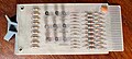 From a DEC KA10, holding nine transistors, 1971
 -
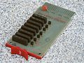 R107 from a TU55 DECtape drive; this board holds seven inverters, each built from one transistor, two diodes, and a hybrid integrated circuit built using flip chip technology.
 -
 DEC PDP-8/E minicomputer, built from multiple quad-height M-series modules


References[edit]
- ^ The Digital Logic Handbook, 1966-67 edition. Maynard, Massachusetts: Digital Equipment Corporation. 1966.
- ^ a b The Digital Logic Handbook, 1968 edition (PDF). Maynard, Massachusetts: Digital Equipment Corporation. 1968. p. 27.
- ^ Bell, C Gordon; Mudge, J. Craig; McNamara, John E. "112 IN THE BEGINNING". Computer Engineering. Retrieved 2022-01-24.
- ^ a b c "FlipChip Technology". Digital Equipment Corporation PDP–7. soemtron.org. Retrieved 2022-01-24.
- ^ a b "Flip Chip latest status". Retrieved 2010-05-28.
- ^ See, for example, the S111, component side, solder side.
- ^ Digital Equipment Corporation, advertisement, Computers and Automation April 1965; pages 6-7.
| Key people |
| ||||||||
|---|---|---|---|---|---|---|---|---|---|
| Instruction set architectures, processors |
| ||||||||
| Computer terminals | |||||||||
| Operating systems | |||||||||
| Programming languages | |||||||||
| Character sets |
| ||||||||
| Bus standards | |||||||||
| Other hardware | |||||||||
| Related topics |
| ||||||||